It might be a good idea to read all these comments through before you begin, especially if your heat sink isn’t doing its job. And do not turn on the computer without a properly attached heatsink!
USE THE INFORMATION AND DIRECTIONS ON THIS PAGE AT YOUR OWN RISK. I DO NOT WARRANT THIS INFORMATION AND WILL NOT BE LIABLE FOR THE OUTCOMES OF USING THIS INFORMATION.
You will basically work into the inside through the keyboard side. I did this on a N5430 but it should be the same for the XE3. NOTE that the order of the procedure might be different for an XE3, so use common sense to figure it out. This is a historical account of what I did. Also, most parts are attached by cables that it is important for you to not pull on. There will always be another method to release the cable that does not involving pulling on the cable. Notice how all the cables fit together nice and flat, you need to put them back this way later.
1. Remove all the screws (something like 12) you can visibly access, these will be on the bottom and rear panel. Make sure you keep track of what screws came from where, you will have about 40 screws once youve gone through all the steps. (A note about the N3xxx series: “there turned out to be *one* screw underneath one of the rubber feet!” –Jeff) (and about a ze41xx: “a row of 5 screws underneath the laptop on the front edge that are hidden under rubber plugs” –Rob)
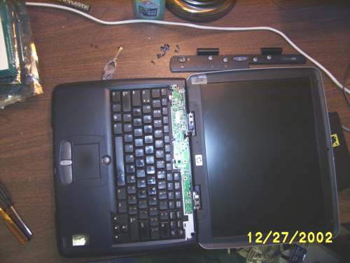
2. Set the laptop rightside-up. Remove the 2 screws from the back of the two screen hinges if you didn’t already. Then open the screen 180 degrees and support it with something so that when we detach it, it will stay put.
3. Plastic above keyboard. Insert a small flat-bladed screwdriver underneath the top of the screen hinge cover plastic, and pry the plastic up a bit from both hinges (see the drawn picture below). You will be removing the plastic piece that has the power switch and status lights and such, above the keyboard. Now that you have gotten it to come up a little bit, you just need to keep pulling on those hinges (and not on the front side, even though it is very tempting to do so. It took me forever to get this piece off but it turns out it has some lips along the front side so you need to angle it out from the back. I thought it would break off but it finally came off OK).

4. Keyboard. Four screws hold the keyboard, unscrew those, remove and unplug the keyboard.
4.5. DVD drive I didn’t need to remove this at all, but “Doug” wrote to me saying that if you are replacing your DVD drive, you just need to remove the screw from the one corner of the hard drive where it is attached, and then you can go ahead and do the replacement without disassembling anything else. BTW, he has a N5290.
5. Circuitry for that status cover. Two screws hold the circuitry for that
status cover from #3, remove them and then lift from the left side. You can leave it connected to the display if you want.
6. Display. Disconnect the display cable from the video circuit. Don’t mess up those DIP switches, they are set for the model of your LCD. Now unscrew the 4 screws that support the display, and set the display to the side. I dont think that the display comes apart any further.
7. Top casing. Unscrew the 6 screws holding the top casing on. Two are toward where the bottom of the keyboard, the other 4 are at the top. There is a plastic clip near the network and phone jacks that you may need to unlatch. There is a cable running to the CD player panel, underneath and attached to this case. To disconnect, lift the upper plastic on the connector on the mainboard, and then the ribbon cable will be released. To reconnect, lift the plastic again, insert the cable, then lock the plastic down again.

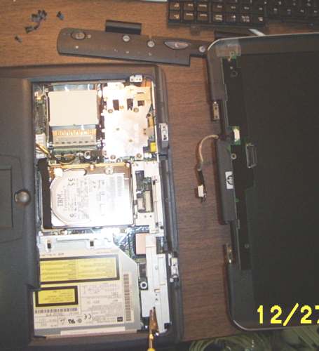
8. Hard drive. Unscrew the 4 hard drive mounting screws (they are attached to the mount and wont come out all the way), and then use the fabric handle to remove the drive.
9. The metal bracket around the outside. There is one screw along the left and one along the right to remove. The center one is optional for you to remove, because I don’t think you need to. (It will separate the bracket into two pieces if you remove the center one.) Note that the bracket has a latch that you need to unlatch next to the network jack. (I think you will need to get to this step in order to fully access the top of the AC adapter plug.)
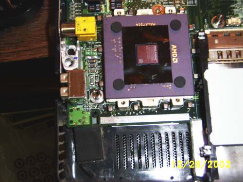
10. The heatsink. (By the way, NEVER turn on the computer without the heatsink properly attached!!) Note that if you remove this you will need a new thermal pad or new thermal
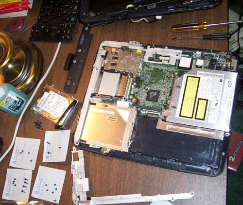
compound (old wont work). You can find out how to apply these sorts of things from other sites on the internet. It is very important to get this right because your chip will fry itself otherwise. So anyhow, there are 4 main screws. They will have attached springs (Something to do with sustaining an even pressure between processor and heatsink.) These 4 are numbered, remove and reinstall in that order. There might be other obvious things needing unscrewing, I had to remove two other screws that seemed to be for aligning the heatsink prior to reattachment.
Note (from Gene James): When reinstalling the heat sink, the key requirement is successively tightening the 4 screws by degrees. So one should turn each a turn in the order of the numbers until they “resist” and then tighten them alternately by slight increases in torque until they are a tight “thumb tight.” This allows the heat sink to settle evenly on the chip. If one tightens one screw first, a large load will be applied to edge of the chip and possibly crack it. I note that the fan is thermostatically controlled to conserve power. One shouldn’t panic if it stops and restarts frequently.
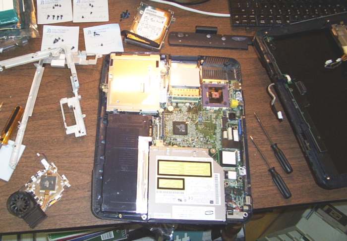
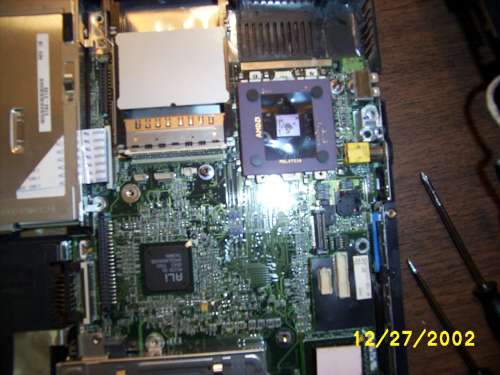
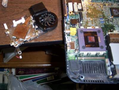
Thats it! (Unless you want to figure out how to remove some more parts…) The laptop I was working on had a problem overheating; when I removed the heatsink I found gobs of dust inside the fan assembly. Using tons of canned air I was able to clean it. I am now looking for some sort of external air filter to prevent recurrence
I can be contacted by emailing “greg (at) cif . rochester . e d u”.
Display Disassembly (contributed by Ken Winstrand)
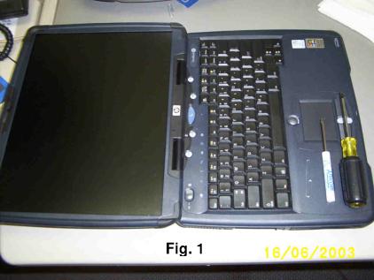
To disassemble the display:
Start with the notebook open 180 degrees as in Figure 1, but with the status panel removed (it isn’t [removed yet] in the picture).
1. Remove the rubber plugs that cover the display screws (Figure 2). Near each corner of the display there is a rubber plug that covers a screw. To remove those plugs, I used a small screwdriver and a paper clip with the end bent at ninety degrees to make a hook. Push down on the plug with the screwdriver, which opens up a gap on the side of the plug, and use the hook to pop the plug out.
2. Remove the four silver screws that hold the display in place.
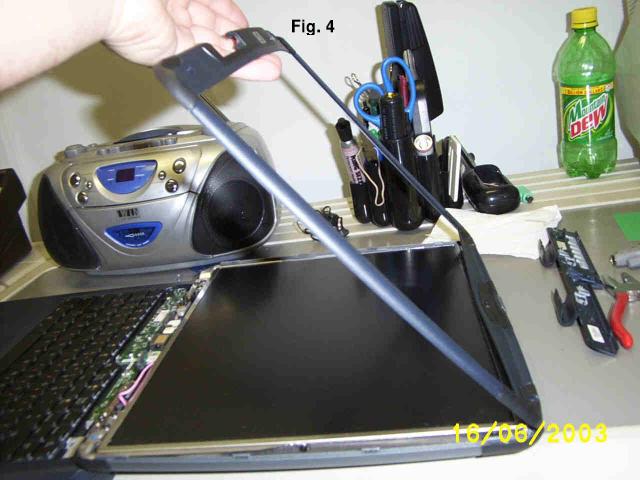
3. Open the sides of the plastic shell that holds the display (Figures 3 and 4).

4. Lift up the plastic on the lower left hand corner and begin to work your way around the edges. You may want to slowly slide a small screwdriver along the crevice to help locate the plastic clips that hold the two halves of the plastic shell together. When you find one of these, just twist the screwdriver or put some inward pressure on the clip
while lifting the plastic.
NOTE: When you reach the sliding release lever at the top of the display, you’ll see that it also helps to hold the shell together. Ignore this for now and repeat step 3 starting from the lower right hand corner.
5. Open the bottom side of the shell. At this point the sides of the shell are open, but the top and bottom are still held together. To open the bottom place your fingers on the plastic edge above the logo and pull toward you. The plastic will pop

open, and now the only thing holding the shell together is the slider at the top.
If you’re just looking to check/change the display cable, you can stop right here. Disassembly beyond this point is possible, as you will see below, but if you go past step 6 reassembly is a PITA.
6. Free the top of the plastic shell from the latching system (Figure 4). Lift the cover from the bottom so that it hinges on the top edge. Pull the slider back so that the latching hook doesn’t hold the cover on. Be gentle and don’t bend the slider or stress the plastic too much, but a fair amount of lifting force is needed before the top piece snaps off.
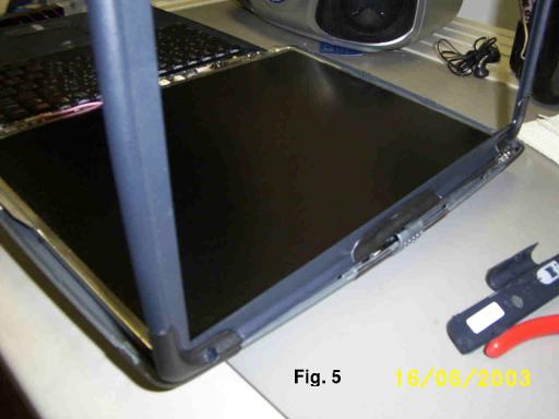
Reassembly Tip: When putting the top half of the plastic back on later, start with the top standing straight up and inserted below the plastic slider (Figure 5). Pull the slider half-way back so the hook will go into the slot, and begin to lower the top into place. This may take
some fancy fingerwork. Eventually you’ll get this assembly to snap back together, just make sure all the parts are lined up and try not to put too much stress on the hook.
———-
I didn’t take it apart any further than that, but you could. Just disconnect the wiring and remove the screws that hold the LCD in at the bottom. To disconnect the wiring, you’d need to have the status panel circuitry and possibly the keyboard or top of the unit off, and I didn’t have the time or the need to go that far. I just wanted to check the wiring to see if it was worn out because the display is flickering. In my case, the display flickers because opening and closing the lid causes the LCD to twist, which obviously isn’t good for it. HP probably should have used more metal in the top half of the shell to keep it
from twisting like that and wrecking the display.
The silver set of display data wires or bus (as opposed to the black wires feeding the step-up transformer for the illumination) is very fragile. Display anomalies (displaying black screen as green with fringes) could be made to disappear by squeezing one part of the bus between my fingertips. Repeatedly doing this also made the fatigue related disorder worse. The only fix is to replace the display bus.
Blogged with Flock
 defeat the powerful Maharajah of India with the promise of honor and glory. After looting the city and capturing a giant hourglass full of sand, a mysterious dagger, and the Maharajah’s daughter along with other treasures, they continue to Azad. A dying Vizier, who had betrayed the Maharajah and aided King Sharaman in return for a share of the spoils, demands to have the dagger, as he was promised his choice of the Maharajah’s treasures. But Sharaman refuses to take the dagger from his son, who captured it first. So the Vizier, who wishes to harness the power of the sands in the hourglass for himself, making him an immortal god and giving him control over time itself, tricks the Prince into opening the hourglass. When the Prince uses the dagger to unleash the Sands of Time from the hourglass, it destroys the kingdom and turns its populace into savage demons. Only the Prince, the Vizier, and Princess Farah, the kidnapped daughter of the Maharajah, remain unchanged due to their possessions; the Prince’s dagger, the Vizier’s staff, and Farah’s medallion.
 finds himself hunted by the Dahaka, the Guardian of the Timeline. Because the Prince escaped his fate, the Dahaka is sent to ensure that the Prince dies and thus restore order to the Timeline.
 Dahaka and successfully alters Kaileena’s (The Empress of Time) fate. While on a ship en route to his home city of Babylon, the Prince tosses the magical medallion overboard, as he no longer needs it. Promising Kaileena that no harm would come to her in Babylon, upon returning he is horrified to learn that his city has been ravaged by war. Additionally, his ship is attacked which results in both the Prince and Kaileena being thrown overboard, although Kaileena is taken prisoner after drifting ashore.
 What a game this has been. Went right down to the wire. Can’t ask for more from a grand final. The crowd erupts as the Indian support staff, coaching staff and remaining squad members charge onto the field.
 Everytime, I see the movie ‘Butterfly Effect’ , how I wish if I could spin back time and start it all over again. The changes I would have created so that I can call my nightmare’s dreams !!!! But I am happy the way everything is going, although my entire is mounted with failures and tear’s of regrets…It’s surprising that I am still surviving, which makes me feel I have a greater purpose left….i believe I have potential’s beyond my imagination. I like to make that that one day.
 I was shocked to see yestherday’s paper. Sanjay Dutt has been found guilty !!!!


 :
: